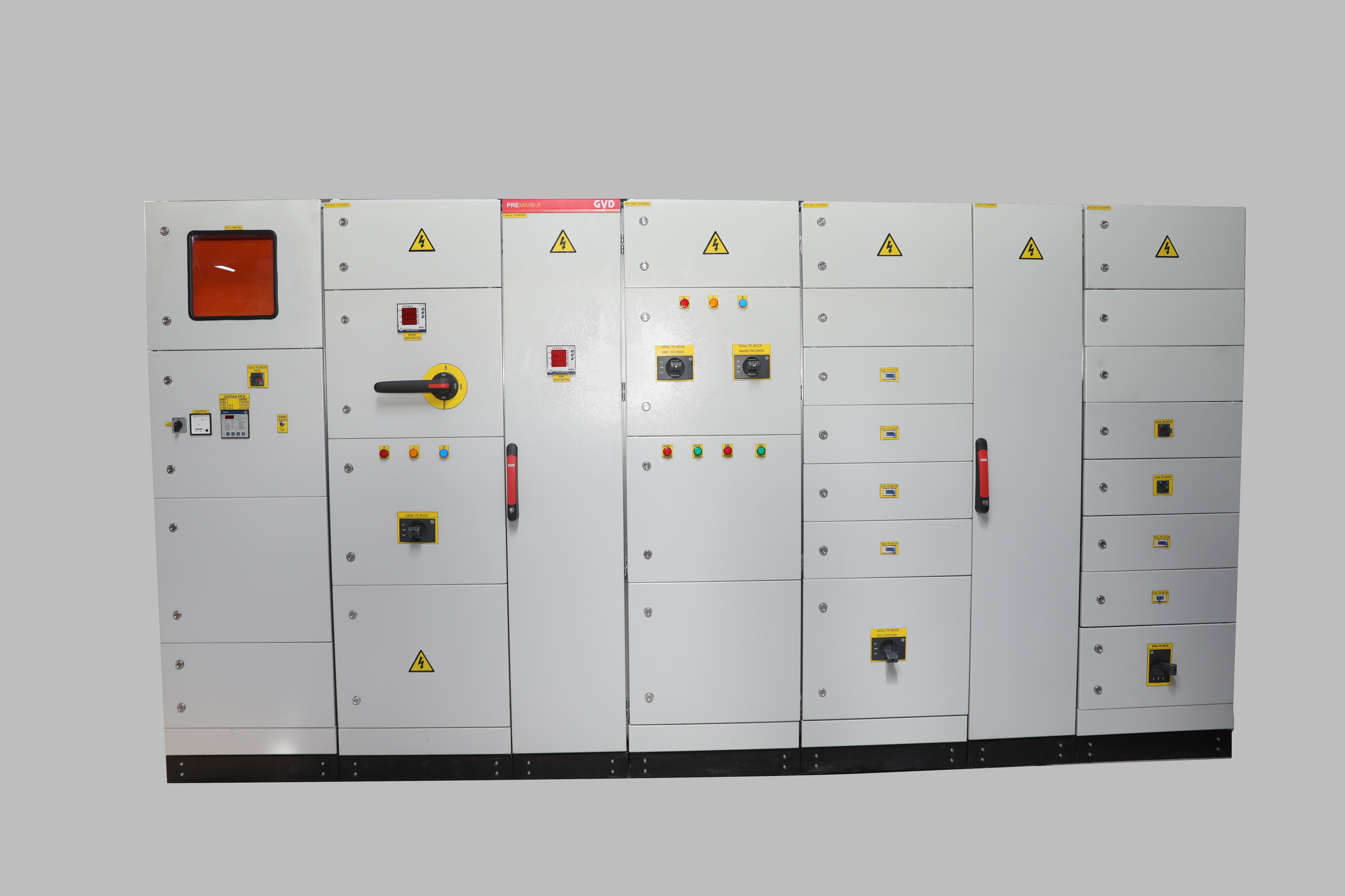
LOW VOLTAGE PANELS
At ABCOS INDUSTRIAL LTD our range of products comprises of PCC (Power Control Centre) Panels, MCC Panels (Motor Control Centre), Automation & PLC Panels, Power distribution boards, AC/DC Drive Control Panels, Automatic Power Factor Correction Panels (APFC), AMF Panels, Feeder Pillars, Meter boards, Motor starters - Direct Online Starter, Star-Delta Starter, Indoor/Outdoor application boards, etc.
Main Low Voltage Panel (Power Control Centre)
- Main Low Voltage Panel (Power Control Centre)
- Form of separation 3b (also available - from 2b, 3a, 4a, 4b)
- Ip 44 protection
- Type tested accessories
- Front & back access
- Panel Dimension - 2000H x 3800W x 600D
- Switchgear used - LARSEN & TOUBRO (also available ABB, SCHNEIDER ELECTRIC, OMRON, TLAC, WINDSOR,SIEMENS).
Motor Control Centre (MCC)
- A motor control center (MCC) is an assembly to control some or all electric motors in a central location.
- It consists of multiple enclosed sections having a common power bus and with each section containing a combination starter, which in turn consists of motor starter, fuses or circuit breaker, and power disconnect.
- A motor control center can also include contactors, overload relays, push buttons, indicator lights, variable-frequency drives, programmable logic controllers, and metering equipment. We generally use ABB, Schneider, L&T switchgears. Panel - Form 3B, types tested, IP44 rated.
- We also do direct online starters, star delta starters rated from 0.37kw to 250kw as per required make.
Automatic Power Factor Correction Panel (APFC PANEL)
- Power factor control boards - APFC Panel mainly used for the improvement of PF up to 0.999 or Unity.
- The Purpose of APFC Panels is to save around 30% energy & provide quality of power to the LT Panels.
- APFC Panel includes a microcontroller-based programmable controller which controls Pf by switching on or off the capacitor banks of suitable capacity as per requirements.
- By reading the reactive load automatically in multiple stages by directly works in the principle of VAR sensing tends to maintain the PF to 0.99 Lag.
- We have capacitors, capacitors contactors, power factor controllers of ABB, Schneider Electric, L&T, EPCOS make.
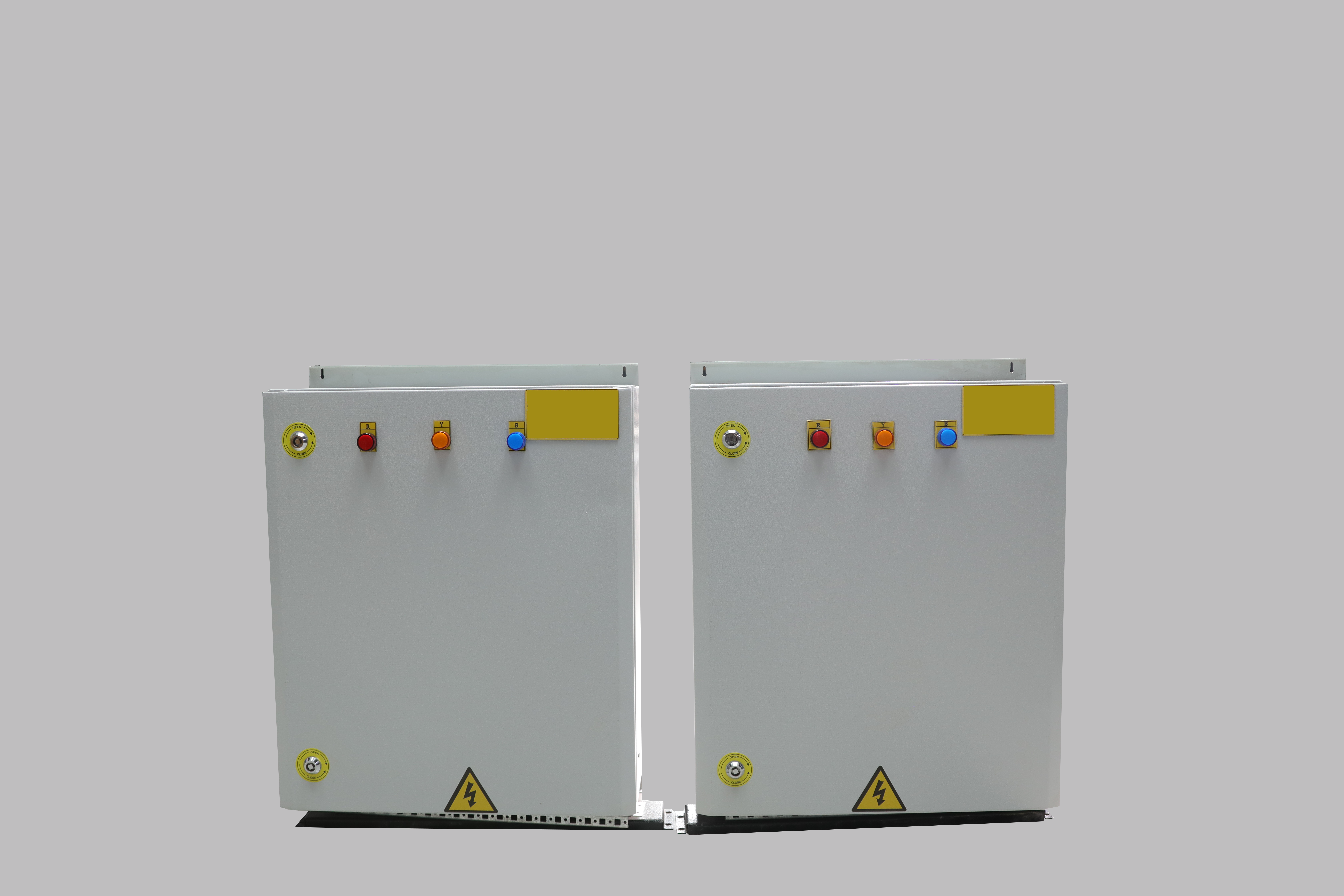
SUB BOARDS, DISTRIBUTION BOARDS & METERBOARDS
- It is generally required after MAIN LV PANEL to distribute power to several nearby Machines, Small Sector units, Small Scale Industries, Building Apartments, Houses, Universities, etc.
- Types - Free standing, Wall mounting, Outdoor type, Indoor type, Form 2B, Form 3B.
- Customer requirements are as per different outgoing ways i.e 4ways, 6ways, 8ways, 12ways etc.
- Meter boards are generally required for Buildings & Apartments. It comes with KPLC meter provision, Kplc cutouts provision, 63/80A DP mcbs, incoming mccb as per requirements.
Practical advices for positioning of circuit breakers inside LV switchboard
Mounting of the different mechanical and electrical components (enclosures, busbars, functional units - circuit breakers, etc.) which constitute the LV switchboard defined by the original manufacturer must be carried out in compliance with the instructions of the manufacturer.
After the preparation of the loose parts to be assembled, the first step is constructing the metal work structure.
For small and medium size LV switchboards the insertion of the components inside the LV switchboard can be carried out more easily by arrange the enclosure horizontally on suitable trestles. Thus, working in this way it is possible to avoid keeping arms up and legs bent as it would be instead with an enclosure in vertical position.
Info!
Obviously, it is suitable to proceed by mounting the apparatus from the centre towards the outside, connecting the cables little by little and inserting them in the relevant cable ducts.
Positioning of the circuit breakers
Here are some general indications for the best positioning of the circuit breakers inside the LV switchboard. It is the panel builder that, since he better knows the details of the plant, the installation place and the actual use, can design the switchboard front in an optimal way.
"A good rule is trying to position the circuit breakers so as to shorten the paths of the higher currents,thereby reducing the power loss inside the LV switchboard with undoubted bene ts from the thermal and economical point of view.
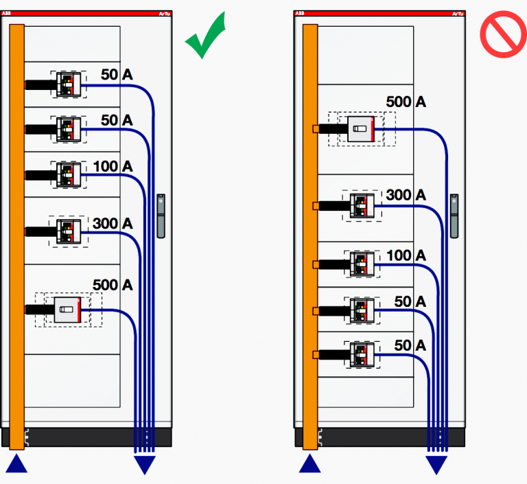
In the case of LV switchboards with a lot of columns, where possible it is advisable to position the main circuit breaker in the central column. In this way the current is immediately divided into the two branches of the LV switchboards and the cross- sectional area of the main distribution busbars can be reduced.


In the example given in the left figure, the main busbar system can be sized for 2000 A, with a considerable economic advantage.
In this case, on the other hand i.e the figure in right side, the main busbar system must be sized to carry 3200 A.
Info!
It is advisable to position the largest and consequently the heaviest circuit breakers at the bottom.This allows greater stability of the LV switchboard, especially during transport and installation.
In electric switchboard the temperature varies vertically:
- The lowest areas are the coldest ones
- The highest areas are the hottest ones
For this reason, it is advisable to place the apparatus passed through by a current close to the rated value at the bottom (more loads) and at the top the apparatus passed through by a current far from the rated value (more discharges).
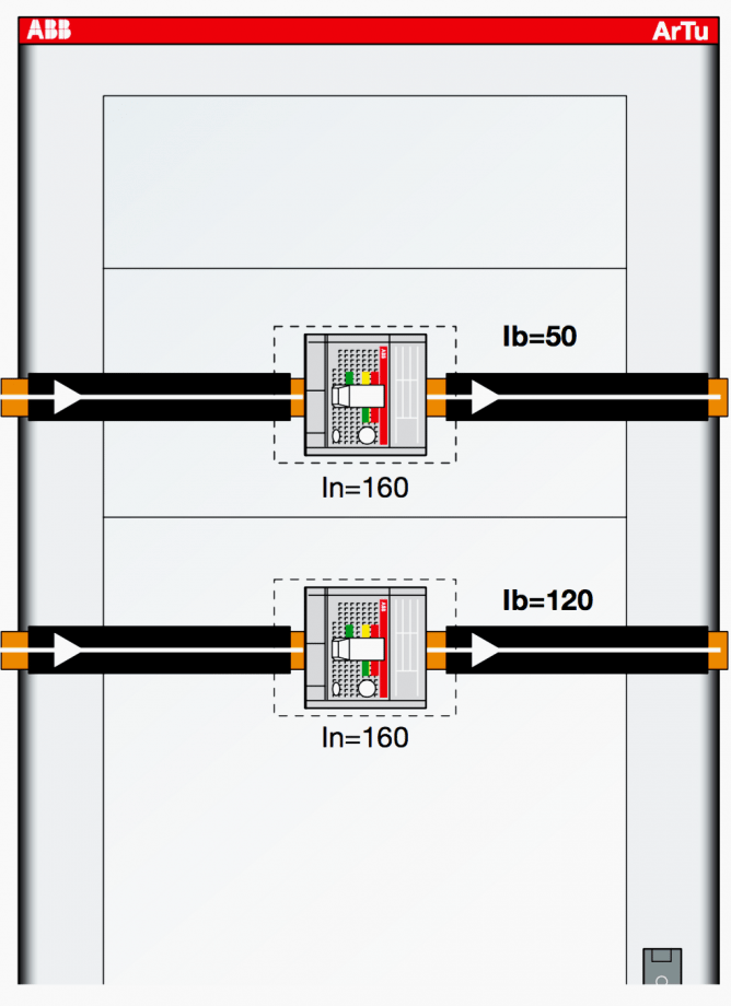
To facilitate the operation of large apparatus it is advisable to place them at a distance of 0.8 to 1.6 m from earth.
Anchoring of the conductors near to the circuit-breakers
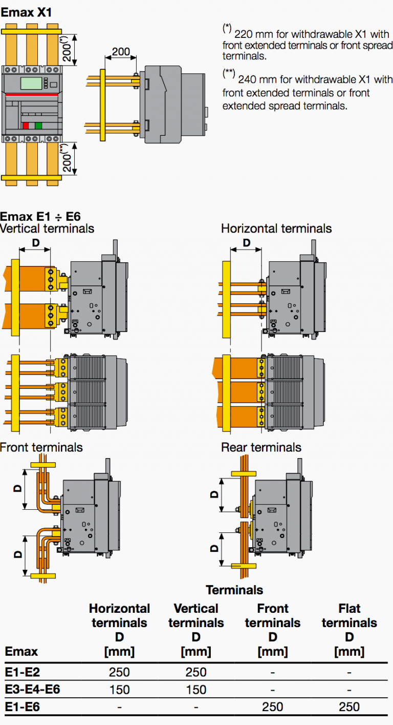
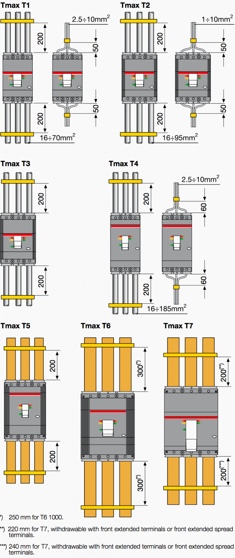
It is necessary for the cables and busbars inside the LV switchboards to be fixed to the structure. In fact, during a short-circuit, the electrodynamic stresses generated in the conductors could damage the terminals of the circuit breakers
Emax circuit breaker
Emax air circuit breakers as shown below an example of the maximum distance in mm (D) at which the first anchor plate of the busbars connecting to the circuit breaker shall be positioned according to the type of terminal and making reference to the highest admissible value of short-circuit current and of its relevant peak.
Tmax circuit breaker
Tmax molded-case circuit breakers as shown below is an example of the suggested maximum distance in mm at which the first anchor plate shall be positioned according to the type of terminal and making reference to the highest peak current value admitted for the circuit breaker..
For more technical information download below files:
